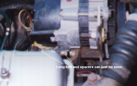
Picture 1: Bottom mounting can just be seen, with long bolt and spacers
Replacing the Dynamo with an Alternator
We had been thinking about fitting an alternator to our Herald 13/60 estate ever since we bought it, and the recent failure of the dynamo (probably due to the halogen headlights and fog light we had fitted for survivial on the moors!) provided a perfect opportunity to do just that. We knew it wasn't a difficult task, but it actually turned out even easier than we expected. Here's what to do:
Firstly, you will need an alternator. Almost any will do, but we used a Lucas one as found in late Spitfires and Ford Fiestas. Some articles we have read (usually American) seem to be dead against Lucas alternators, but the one in our Spitfire 1500 provides ample power for halogen lights, fog lights, radio etc., and has the added advantage that the spade connectors for the dynamo will fit straight on, avoiding an extra cut in the loom to fit a new plug. As the Herald is our main daily transport and reliability and time were important, we bought an exchange alternator from a local motor factor for just over Ł30 (they even took the dead dynamo as exchange). This should have been hassle-free, but as Sod's Law dictates in these situations, we were sold a duff one (regulator didn't work), then swapped it for another duff one! At the time of writing, the Herald is using the Spitfire's alternator (but you shouldn't be so unlucky, we hope!). If you have more time, there are still plenty of this type of alternator around in scrap yards, so you could save some money here. You should make sure you use a proper solid alternator drive pulley - don't be tempted to graft the one off your old dynamo onto the alternator, as these are riveted and have been known to break with the extra force needed to drive an alternator at full output.
The first thing we did was to make the alternator fit the car. We tried to find a "real" alternator bracket from a Spitfire or Dolomite, but failed, so we decided to try to make some brackets ourselves. Trial fitting of the alternator proved that we didn't need to! The only difference is that the rear bottom mounting of the dynamo bracket is further back than it needs to be for the alternator. We could have made a new bracket quite easily out of metal strip, but found that a long bolt and lots of spacers was perfectly secure, and much easier (see picture 1). The pulleys aren't quite perfectly lined up, but the long drivebelt in the Herald allows for this slight misalignment without problems (we've done over 1000 miles with this arrangement with no unusual wear).
Picture 1: Bottom mounting can just be seen, with long bolt and spacers
Next you need to get the fan belt to fit. The Herald one was now too short, so we tried a Spitfire 1500 one (1088mm), which was slightly too long. We couldn't find a belt the right length (about 1060mm is what it would need to be), so we decided to extend the top adjusting bracket to make the Spitfire belt work. All that was needed was a short length of metal strip (we had some 3mm thick aluminium lying around which did the job, and was easy to cut and drill) about 3" long with a hole at each end. One end was bolted to the alternator with a spacer the same thickness as the adjusting bracket, and a bolt through the other end slides in the adjusting slot (see picture 2). This was a very simple solution to the problem, but we would obviously need to remove the extension before lifting the engine or the aluminium would probably break!
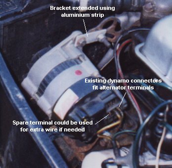
Picture 2: Top mount extended with metal strip and extra bolt
Obviously, if you have "proper" alternator mounting brackets you would use those, but our mounting shows that it can be done with the dynamo brackets and minimal effort (although it doesn't look that pretty!)
Now for the wiring modifications... First, disconnect the positive terminal from the battery to avoid zapping anything while you are cutting and joining wires. The two spade connectors that used to connect to the dynamo will fit straight onto the new alternator if you have used a Lucas one like we did. The thick wire goes to the output terminal (either of the two big ones on our alternator, as they are connected together internally, but check yours) and the thin one goes to the small terminal on the Lucas (charge warning light connector).
All the modifications are to the wiring at the control box (the black box on the bulkhead next to the battery). Unplug all wires from the control box and remove it (it is held on by two screws). The black earth wire is no longer needed, so just insulate it and tie it out of the way. The thin brown and yellow wire connects to the thin brown and green wire (this works the charge warning light). All the remaining wires (two thick, rest thin, all brown or brown with a stripe) must be connected together, incorporating a fuse box if you wish (see below). We didn't put a fuse box in, but may do in the future if we find a suitable one that would fit nicely on the bulkhead. We just stripped the wires back, twisted and soldered them. If and when we want to add a fuse box, it will be easy enough to unsolder the joints. Make sure you insulate the connections well (heat shrink tubing is much more secure than tape) and tie them up tidily with cable ties to avoid the joints taking too much physical strain, if only to make life easier during soldering (the wires are very stiff and tend to try to pull the joints apart if not tied).
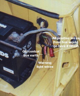
Picture 3: How the wiring looks with no control box.
Fuse box could go here in future.
In summary, this is what you need to do with the wires from the control box:
Black
Not used - just insulate and tie up.
Thin brown & yellow (to warning light)
Thin brown & green (from warning light connection of alternator)
Connect together.
All others (brown with or without coloured stripe)
Connect together (incorporating fuses if required).
The two thick wires should be joined unfused (battery charging) and the others go to various
circuits (see wiring diagram in workshop manual) and could be fused as required.
Some people recommend that you fit a thicker wire from the alternator output to cope with the potentially higher current. The wire in our Spitfire 1500 is slightly thicker than the Herald one, but not much, and plenty of people use the standard Herald wire with no problems, so we left ours alone, but we'll be keeping an eye on it for the teething period to make sure there are no signs of overheating. The easiest way to beef up this connection would be to add a second wire from the alternator output (our Lucas alternator has a spare terminal that could be used) to the positive side of the starter solonoid. This extra wire could be tied along the existing loom and would be much easier than trying to replace the original wire buried in the loom. Other people's experience has shown that if the loom is in good condition and you don't try to draw a huge current for a long time by adding lots of rally lights or similar, the original wire is good enough. After 1000 miles with this setup (mostly in the dark and rain with full-beam lights, wipers and blower running), we are happy that the existing wires are up to the job.
Finally, check all your connections thoroughly, make sure the alternator is mounted securely and the belt is at the correct tension, make sure no tools are lying around in the engine bay ready to fly off and hit something when you start the engine. When you are happy with your work, reconnect the battery and test.
As we said earlier, this is an easy job as long as you are confident and have a bit of practice at soldering (and a big soldering iron - the main output wire is very thick and a high powered iron is needed to make a good joint before the heat spreads and melts the insulation - we used a 50 Watt iron, and you would probably struggle with a normal 25 Watt one). It took us about an hour including making the brackets, and that was outside dodging the rain and hail of a Dartmoor winter!
If you want to convert your car, I hope this has proved useful. The details obviously relate to our 13/60, but should be very similar for other Heralds. Above all, be careful and don't tackle the job if you are unsure of anything. Think before you cut! We would be happy to discuss our experiences in person either by email or by telephone (see Courier local area news).
Rob & Helen
(with thanks to Roy Arscott for telling us what to connect to what!)
The following has been sent to us by Con O'Kelly and includes wiring details for other Triumph models:
Herald 1200 and 948 models
First ensure that the car has been converted to Negative earth if necessary.
Alternator connections
Colours at the dynamo/alternator should be a heavy Yellow with a large (9.5mm) lucar terminal and a thin Yellow/Green with a small (6.3mm) lucar terminal
Connect these to the appropriate alternator terminals. See also ‘Additional wiring’, below.
Control box
This should be an RB106/2 type with 5 terminals: A1, A F, D and E.
A1 feeds lighting and ignition, A feeds battery, starter motor and horns. D receives charging current from the dynamo.
Disconnect the Black wire from the terminal E. This disables the Control Box
Disconnect the Yellow/Green from terminal F. Disconnect the thin Yellow wire from the terminal D. Connect these two wires together. They control the ignition/charging indicator light.
Disconnect all remaining wires from:
A1 (browN/blUe),
A (browN) and
D (heavy Yellow) [charging wire].
Connect all of these wires together with a suitable connector:
The Big connection
This conversion requires that a number of large wires, (browN/blUe and browN) are connected together and to the charging wire from the alternator (heavy Yellow). This connection carries all main electrical power and is connected directly to the positive terminal of the battery. It is essential that this connection is electrically sound, with minimum resistance, and that it is effectively and robustly insulated as any short circuit to earth may well lead to a vehicle fire and is very likely to cause wiring to be burnt out. Ideally the connector should be firmly mounted to prevent movement and abrasion.
An elegant and effective connector can be made by stripping out the internals of an unused RB106 type regulator control box and connecting terminals; D,A and A1, either by soldering heavy gauge wire between them, or screwing heavy gauge copper sheet across them. This allows these wires to be connected to their original terminals, thus retaining the original look. The Yellow/Green and thin Yellow wires need to be connected in some other way, unless a piggyback connector is used on the F terminal.
Additional wiring (optional)
It is worthwhile to increase the capacity of the wiring to cater for any heavy charging currents (e.g. charging a flat battery). This can be done as follows, using suitable connectors.
Fit a heavy gauge brown (or perhaps Yellow) wire with a large (9.5mm) lucar connector to the unused large terminal on the alternator. Bind the wire to the loom and run it to the battery side of the starter solenoid, connecting it with a ring terminal.
Herald 13/60
The car should be wired as Negative earth, but it is worthwhile checking.
Alternator connections
Colours at the dynamo/alternator should be a heavy browN/Yellow with a large (9.5mm) lucar terminal and a thin browN/Green with a small (6.3mm) lucar terminal
Connect these to the appropriate alternator terminals. See also ‘Additional wiring’, below.
Control box
This should be an RB106/2 type with 5 terminals: A1, A D, F and E.
A1 feeds lighting and ignition, A feeds battery, starter motor and horns. D receives charging current from the dynamo.
Disconnect the Black wire from the terminal E. This disables the Control Box
Disconnect the browN/Green from terminal F. Disconnect the thin browN/Yellow wire from the terminal D. Connect these two wires together. They control the ignition/charging indicator light.
Disconnect all remaining wires from:
A1 (browN/blUe),
A (browN) and
D (heavy browN/Yellow) [charging wire].
Connect all of these wires together with a suitable connector:
The Big connection
This conversion requires that a number of large wires, (browN/blUe and browN) are connected together and to the charging wire from the alternator (heavy browN/Yellow). This connection carries all main electrical power and is connected directly to the positive terminal of the battery. It is essential that this connection is electrically sound, with minimum resistance, and that it is effectively and robustly insulated as any short circuit to earth may well lead to a vehicle fire and is very likely to cause wiring to be burnt out. Ideally the connector should be firmly mounted to prevent movement and abrasion.
An elegant and effective connector can be made by stripping out the internals of an unused RB106 type regulator control box and connecting terminals; D,A and A1, either by soldering heavy gauge wire between them, or screwing heavy gauge copper sheet across them. This allows these wires to be connected to their original terminals, thus retaining the original look. The Yellow/Green and thin Yellow wires need to be connected in some other way, unless a piggyback connector is used on the F terminal.
Additional wiring (optional)
It is worthwhile to increase the capacity of the wiring to cater for any heavy charging currents (e.g. charging a flat battery). This can be done as follows, using suitable connectors.
Fit a heavy gauge brown (or brown/yellow) wire with a large (9.5mm) lucar connector to the unused large terminal on the alternator. Bind the wire to the loom and run it to the battery side of the starter solenoid, connecting it with a ring terminal.
Spitfire 4, Mk 2, Mk3, Vitesse 1600 and 2 litre models and GT6 Mk 1
Spitfire 4 and Mk 2 and Vitesse 1600 must first be converted to Negative earth if this has not previously been done.
Alternator connections
Colours at the dynamo/alternator should be a heavy browN/Yellow with a large (9.5mm) lucar terminal and a thin browN/Green with a small (6.3mm) lucar terminal
Connect these to the appropriate alternator terminals. See also ‘Additional wiring’, below.
Control box
This should be a three bobbin RB340 type with 6 terminals: 2 x B, F, WL, D, and E.
Disconnect the Black wire from the terminal E. This disables the Control Box
Disconnect the browN/Green from terminal F. Disconnect the thin browN/Yellow wire from the terminal WL. Connect these two wires together. They control the ignition/charging indicator light.
Disconnect all remaining wires from:
B (browN)
D (heavy browN/Yellow) [charging wire].
Connect all of these wires together with a suitable connector:
The Big connection
This conversion requires that a number of large wires, (browN and heavy browN/Yellow) are connected together and to the charging wire from the alternator (heavy browN/Yellow). This connection carries all main electrical power and is connected directly to the positive terminal of the battery. It is essential that this connection is electrically sound, with minimum resistance, and that it is effectively and robustly insulated as any short circuit to earth may well lead to a vehicle fire and is very likely to cause wiring to be burnt out. Ideally the connector should be firmly mounted to prevent movement and abrasion.
An elegant and effective connector can be made by stripping out the internals of an unused RB340 type regulator control box and soldering heavy gauge wire between terminals B and D and, separately between F and WL. This allows all the wires to be connected to their original terminals, thus retaining the original look.
Additional wiring (optional)
It is worthwhile to increase the capacity of the wiring to cater for any heavy charging currents (e.g. charging a flat battery). This can be done as follows, using suitable connectors.
Fit a heavy gauge brown or brown/yellow wire with a large (9.5mm) lucar connector to the unused large terminal on the alternator. Bind the wire to the loom and run it to the battery side of the starter solenoid, connecting it with a ring terminal.